6. НОВЫЙ ИНТЕРФЕРОМЕТР ДЛЯ ИЗМЕРЕНИЯ СКОРОСТИ ДВИЖЕНИЯ ТЕЛА ОТНОСИТЕЛЬНО ЭФИРА
Для того, чтобы успешно измерять скорость Земли или движения
тела относительно эфира, необходимо иметь интерферометр, который вследствие движения
показывал бы легко измеримое перемещение между частями разделенного луча,
которое создают интерференцию. Произведенный анализ показывает, что это
требование не выполняется интерферометром Майкельсона или любым другим
известным интерферометром. Тем не менее, это выполнимо нашими новыми
интерферометрами, которые значительно лучше, чем кажется на первый взгляд.
Они очень чувствительны, небольших размеров и простой конструкции.
Во-первых, они разрабатывались, чтобы измерить скорость движения относительно
эфира, что должно подтвердить существование эфира. Их использование также
исключает неопределенность в связи с Лоренцевым сжатием длины тела из-за
движения через эфир. С этим интерферометром эффект Допплера не имеет влияния
на величину перемещения интерференционной картины.
 |
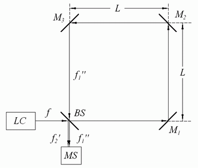
Схема одного нового интерферометра представлена на Фиг. 6.1,
где  лазер с коллиматором,
  -
лучевой делитель лазерного источника света, полупрозрачное зеркало,
установленное под углом 45° по отношению направления лазерного излучения;
 ,
,  и
и  - зеркала;
  - фотоны из коллимированного лазерного источника излучения;
 - фотоны, отраженные сплиттером;
 - фотоны, прошедшие через сплиттер;
 - измеритель сдвига между лучами
или экран для наблюдения сдвига интерференционных полос и
 - длина стороны интерферометра.
Экстремальная когерентность лазерного излучения
позволяет этому интерферометру функционировать стабильно.
Когда система находится в покое относительно эфира,
те части луча (фотонов), которые находятся дальше друг от друга для
 или дсвинутые на время для
 , создают интерференцию, где
 - длина одной стороны интерферометра и
 - скорость света.
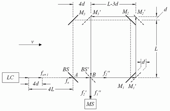
На фиг. 6.2, мы можем увидеть схему функционирования
интерферометра, когда он перемещается со скоростью
 через эфир в направлении лазерного излучения
и когда это движение принято во внимание.
На этой фигуре
  смещение всей системы и также
всех частей интерферометра, в то время, как часть луча, которая была пропущена через
сплиттер, прошла из сплиттера
  к зеркалу
 .
.
 |
The initial position of the mirrors and the beam splitter is marked
with a full line. The position of these components at the moment of the
arrival of the studied ray is marked with an interrupted line. So, the
mirror  is shifted by
  into the position
  ,
the mirror
  is shifted by
 in the position
  , etc.
For easier explanation of the interferometer's function,
the shift  in the figures is considerably increased in relation to the interferometer
sides.
When the interferometer starts to function,
the part of the beam  ,
is reflected from the splitter in the form of the beam
  which
is not an object to be observed or taken into consideration. The other
part of that beam
  passes through the splitter in the form of
the beam
  in the direction of the mirror
 . During the
time it takes that beam to reach the mirror
  from the splitter,
all mirrors and the splitter shift in the direction of the interferometer's
motion for the distance
  .
While this beam passes from the mirror
  to the mirror
  all mirrors and splitter
move for another distance
  .
So by the time the beam
  reaches the splitter moving through
the interferometer, which is shifted in the direction of the system's motion
for the distance
  . Inside the interferometer,
the beam
  passes the total way
 |
(6.1) |
and then a greater part of the beam  passes through the
splitter in the direction of the shift measurer and joins up for the purpose
of interference together with the reflected beam
  which, at
that moment reaches the splitter from the direction of the laser. When
there is no motion of the interferometer relatively to the ether, photons
from the plane of the wave whose mutual shift is
  interfere
because the reflected part of the beam
  is late for
  in relation to the transmitted part of the beam
  . However, when the
interferometer moves in relation to the ether, the beam splitter shifts
forward for
  during the time while the beam
 passes
all four sides of the interferometer. Because of that the beam
  interferes with the beam
  which is late for
 . So, that
difference of the ways between the two beams, which interfere, is
 |
(6.2) |
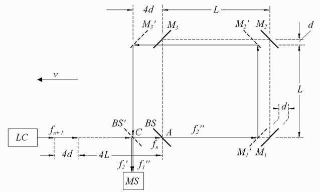
If we rotate the system through 180 degrees, then the interferometer in the ether will move in the opposite direction to the direction of the laser radiation, as it is shown in Fig. 6.3. So, the beam which has been transmitted through the splitter will pass the following way in the interferometer
 |
(6.3) |
and during this time the splitter moves in the direction of the interferometer's
motion for  and the difference of the paths of the interfered
beams is
 |
(6.4) |
From Eqs. (6.2) and (6.4) it works out that by rotating the system through 180° we obtain the difference of the shifts, which is measured by the shift measurer
 |
(6.5) |
 |
For the time while beam  travels along path
  inside
the interferometer at velocity
  ,
the beam splitter passes the way
  at a speed
  , so we have the following relation
 |
(6.6) |
and from there and Eq. (6.5) we obtain
 |
(6.7) |
[In consideration we take that  .
So
.
So  and
and  .
The exact equation is
  , but since
  then we can write
  .]
.]
The shift presented by Eq. (6.7) is rather big and there are no
difficulties in measuring its magnitude and also a velocity of a body motion relative
to the quiescent ether. This can be done with great accuracy even under
the assumption that this velocity is only 30 km/s or considerably less.
For example, if  = 30 km/s and
  = 0.1 m then
 = 8·10-5 m at rotation of the
interferometer through 180°. If rotation of the interferometer is just 1°,
the mutual shift of the interfered beams would be about 0.444·10-6 m.
As can be seen this interferometer is very sensitive and because of
that the  side should be small. For better stability, the interferometer
has to be compact, for instance to be made out of glass in the shape of
a cube of small dimensions. Three lateral sides of the cube should be mirrors
and the fourth should be a semi-mirror, beam splitter.
In order to reduce disturbance arising from repeated returns part of
the beam  into interferometer, and also for the sake of equalizing
the intensities of the interfered beams, one mirror at least should be
semi-transparent. In conformity with it the beam splitter would transmit
more than it would reflect.
Measurements taken with the interferometer like this eliminate any
dilemma in connection with questions about the existence of the cosmic
absolute quiescent ether and about the contraction of bodies, which move
through the ether.
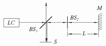
In Fig. 6.4 a new and simpler interferometer is given with the same
purpose as the previous one where:  is a laser with a collimator,
  and
and  are a beam splitters,
 is a mirror or a beam
splitter and
  is a screen for observing interference which appears
between the laser beams reflected from the beam splitter
  and
from the mirror
  .
.
 |
Сдвиг интерференции, вызываемый движением интерферометра относительно эфира благодаря повороту интерферометра на угол 180° дается выражением
 |
(6.8) |
where  is the distance between
the beam splitter
  and mirror
  ,
,  is a speed of interferometer motion in relation
to the ether and
  is light velocity.
One side of the  and
and  would be coated with an
antireflection coating, and the other side with reflection coating where
reflection would be about 50% in case of
  and about 38%
in case of
  . For the sake of better stability of the interference
fringes this interferometer also would be made from glass as a compact
interferometer.
Новый интерферометр является результатом исследования возможности
создать простой интерферометр, который был бы значительно более чувствительным,
чем любой другой уже существующий. Фактически, моя цель была в том, чтобы
изобрести такой интерферометр, который мог бы подтвердить мою гипотезу о
существовании земного эфира. Как это раньше было показано, я достиг того,
к чему стремился. Новый интерферометр имеет эту возможность, во-первых,
благодаря чрезвычайной когерентности лазерного излучения, которое используется
этим интерферометром.
на главную
|
|